Ambient Occlusion
- What is ambient occlusion?
- Why is it used?
- Current Techniques
- Blender implementation
- Introduction
- Birth of a new technique
- Reflection Occlusion
- Ambient Occlusion
- Conclusion
- Real Time Ambient Occlusion
- Bibliography
Check my video (˶ᵔ ᵕ ᵔ˶)
Introduction
Understanding reality and representing it accuratelly has been an active research field for centuries on all artistic disciplines.
Movements like impressionism have tried to find better ways of illustrating reality than reality itself (perceived reality). They depict objects as light strokes, avoiding a defined shape or form. Light representation affects emotions, credibility, intention and context.
In recent years we have seen an increasing graphical improvement on computer generated images trying to get closer to reality. This provided new techniques to simulate light behavior on virtual enviorments.

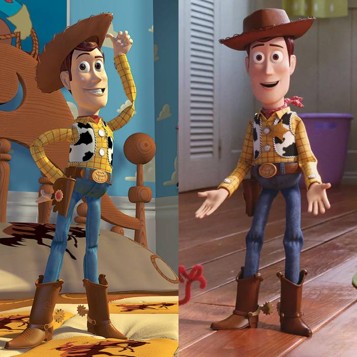
Computer generated films such as Toy story, illustrates the evolution of phisically based rendering techniques (PBR). Even high stylized games are not free of this requirement of respecting light behavior since it directly impacts the viewers inmersion into the story.
That is why some rules are constant for good looking media such as light propertyes (color, intensity, spectrum, …) and light interaction (global illumination, ambient occlusion, transparency, caustics, … ).
Global Illumination & Image Base Lighting
These concepts are out of scope but I will summarize them.
Global Illumination
Global Illumination is a collection of techniques to simulate realistic lighting.
One of the characteristics of light is that it bounces from one surface to another. Calculating all bounces of light reaching each surface point is expensive but provides good results. For this calculations we use path tracing and ray tracing algorithms.

Algorithms like ray tracing and path tracing simulate full global illumination, but they require significant processing power. In exchange, they provide close to real light occlusion and do not need to use ambient occlusion techniques. AO can still be used for enhancing some effects.
This techniques are so realistic because they use the scene geometry and textures to calculate the light for a certain number of iterations (global illumination). This iterations are known as bounces, the number of times a light path collides on a surface and changes direction.
Example Renderers:
- Ray tracing renderer: Arnold, V-Ray, or Mental Ray
- Path tracing renderer: Cycles (Blender), LuxCoreRender, or Octane Render
Cycles, for example, is a path tracing renderer integrated in Blender that simulates global illumination by tracing the paths of many light rays per pixel.
To simplify or “fake” global illumination we could place lights from all directions by “gessing” how the surface should look. Whith this strategy we avoid computing global illumination and we only use a single bounce from each light.
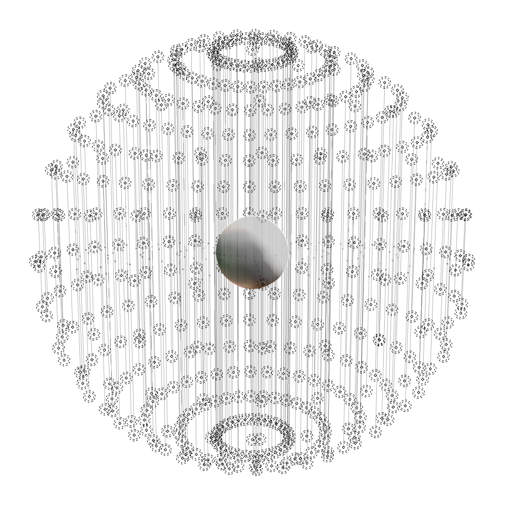
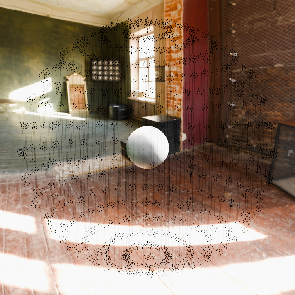
Image Base Lighting
Instead of placing hundreds of lights in the scene, we can group them into an image. This images are called: environment texture, cube map, HDRI, spherical map… Each one with its own characteristics.
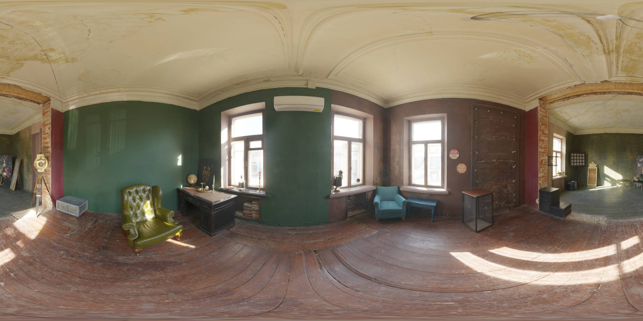
For global illumination we will calculate light and bounces assuming the environment image are virtual light placed really far.
For Image Based Lightning we will use it as a projected texture on the surface making the calculation almost instant compared to Ray Tracing or Path Tracing. One limitation of IBL is that we do not take into account occlusion, buuuuut… we are trying to overcome that.
RESUME: The most physically accurate approach for rendering is by ray trancing and path tracing. Real time techniques require a global illumination simplifications, usually Image Based Lighting techniques. This simplifications have limitations that we must overcome.
Birth of a new technique
Ambient Occlusion was first used in “Pearl harbour” to store the quantity of ambient light that reaches the surface of an airplane 11. This same technique was used in Cruise Control a few years before to determine the reflection intensity of each window. Find more information on [1: Ben Snow: the evolution of ILM’s lighting tools; ; 2014].
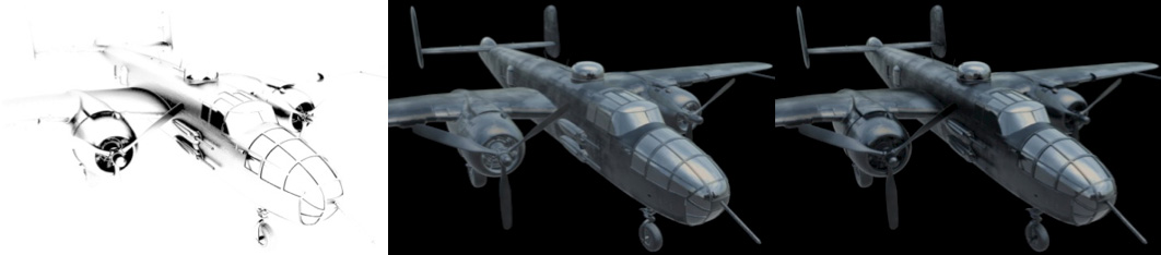
We already mentioned that this technique can be expensive and time consuming. Luckily for them, films do not require real time processes even though its still desired. For this productions, they baked geometry occlusions in image sequences and use it in the rendering pipeline as another texture.
We are going to explore two different techniques developed by ILM: Ambient Occlusion and Reflection Occlusion. The reason they developed two techniques is because materials are usually composed of two components: Diffuse and Specular.
We will need to evaluate how much light reaches a point for both of this components.
Reflection Occlusion
We will start by explaining Reflection Occlusion. It corresponds to the $fr_{specular}$ component of the light.
Reflection Occlusion (RO) is a rendering technique used to estimate how much reflected light reaches a surface point. In essence, it simulates how exposed each point is towards the reflection vector.
First, compute the reflection vector $r$ of the view direction $v$ (from the surface to the camera) against the normal $n$ using the 5 formula.
Now, define the Reflection Occlusion at point $p$ using a visibility function:
Where the visibility function $V(p, \omega)$ is defined as:
Where:
- $r$: Reflection vector computed from 5.
- $V(p, \omega)$: Visibility function that returns 1 if direction $\omega$ from point $p$ is unoccluded, 0 if occluded.
- $d(p, \omega)$: Distance to the nearest surface intersection along direction $\omega$ from point $p$.
- $\epsilon$: Maximum occlusion distance threshold.
In other words, we cast a ray from the surface point $p$ along the reflection direction $r$ and check if it hits any geometry within distance $\epsilon$ using the visibility function. If it does, the reflection is considered occluded ($V(p,r) = 0$); otherwise, it’s unoccluded ($V(p,r) = 1$).
Other visibility functions are possible, providing smoother results. We use the boolean approach because it visualizes the concept more clearly and shows the limitations.
Here, $\epsilon$ represents the radius where we are detecting collisions. If $\epsilon$ is too small we may end up not detecting any collision and assuming the surface is exposed to the enviorment map even if it is enclosed in a room for example. The distance to the walls would be big, but still it should not be considered exposed to an environment map.
Remember, this technique is view dependent therefore we need to compute it each frame or bake it if we know the camera position and the scene will not be modified.
Computation
The process to obtain the Reflection Occlusion path is:
- Get the surface normal and position.
- Get the camera position.
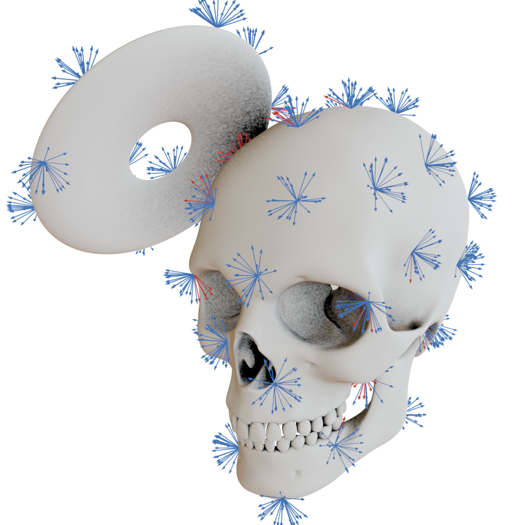
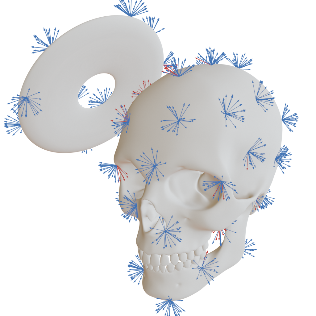
- Calculate the reflection vector from the three previous variables 5. It will look like figure 12.
- Use some technique to calculate ray intersections from the surface to the rest of geometry 13.
- Store the collision distance per fragment.
- Use it to darken the Reflection Map with a shader.
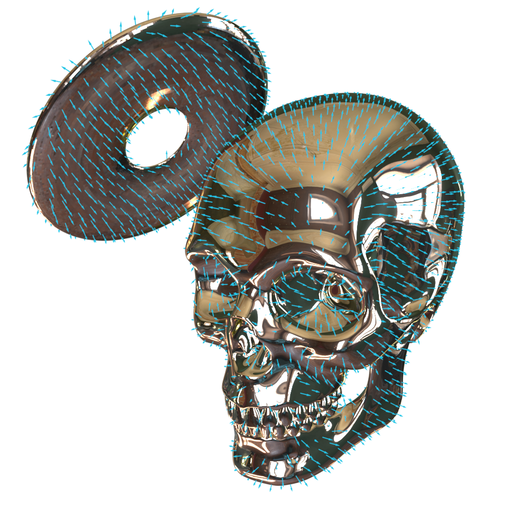
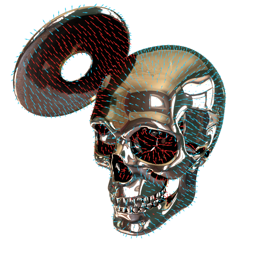
The arrows in this images are the reflection vectors computed with 5
The limitation of this technique is that, instead of reflecting the collided surface, it just darkens the fragment. For general purposes this is enough.
In path tracing renderers, you are usually provided a parameter to choose the bounces limit. This is of course more realistic, but may take several minutes 14. We also avoid showing incorrect reflections when occluders are far since we dont use IBL techniques.
As easy and powerful this method may seem, it is not used because of the processing time it takes for each frame to calculate collision. New techniques like Ray Tracing may be able to provide real time Reflection Maps in the future.
Ambient Occlusion
Finally!!, we get to point of the post. We are now on the Diffuse side of the formula 3.
Ambient Occlusion (AO) is a rendering technique used to estimate how much ambient light reaches a surface point. In essence, it simulates how exposed each point is to surrounding light, based on nearby geometry.
AO follows the same principle as Reflection Occlusion, but instead of checking a single reflection direction, we must evaluate all directions from which light can reach the surface point.
This difference stems from the fundamental behavior of diffuse materials: while specular reflections bounce light in a single direction (like a mirror), Lambertian materials (also known as perfectly diffuse surfaces) absorb incoming light from any direction and scatter it uniformly in all directions. Therefore, to accurately compute ambient occlusion, we need to sample the entire hemisphere of possible incoming light directions.
At this point, you may be a bit confused on what exactly is “diffuse” or “specular” and what is the difference between this concepts and the irradiance of the surface point.
I want to make the following very clear: In Bidirectional Reflectance Distribution Function (BRDF) we are describing how light reflects off a surface, detailing how incident light from one direction is reflecting into another, considering angles, material properties, wavelenghts and much more.
We are using some concepts related to BRDF because there is a lot of relation between how BRDF behaves and how AO+RO behave BUT we are one step early on the pipeline.
We are evaluating the directions and quantity of light that we will feed to the BRDF to produce a rendeder.
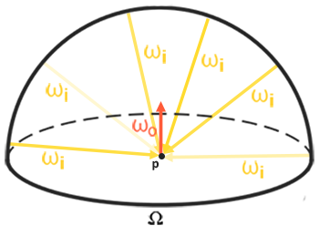
Since global light arrives from all directions in a hemisphere 19, we integrate the visibility function $V(p, \omega)$ over that hemisphere, weighted by Lambert’s cosine law:
Where:
- $\Omega$: Hemisphere centered around the surface normal $n$.
- $V(p, \omega)$: Same visibility function used in Reflection Occlusion.
- $n \cdot \omega$: Lambertian cosine weighting — directions aligned with the normal contribute more.
This formula computes how much unblocked ambient light reaches point $p$ by averaging visibility across all incoming directions.
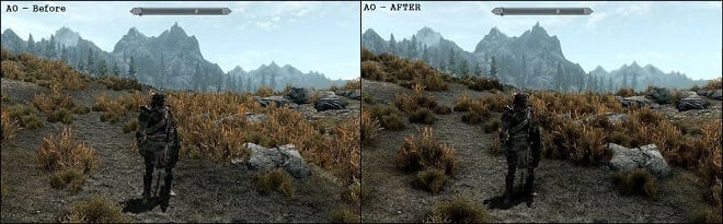
In the real world, light rays are often blocked or “occluded” by objects. This effect happens naturally and gives surfaces subtle shadows in creases, corners, and areas where objects are close together. Recreating this effect adds a layer of realism to CGI scenes (15).
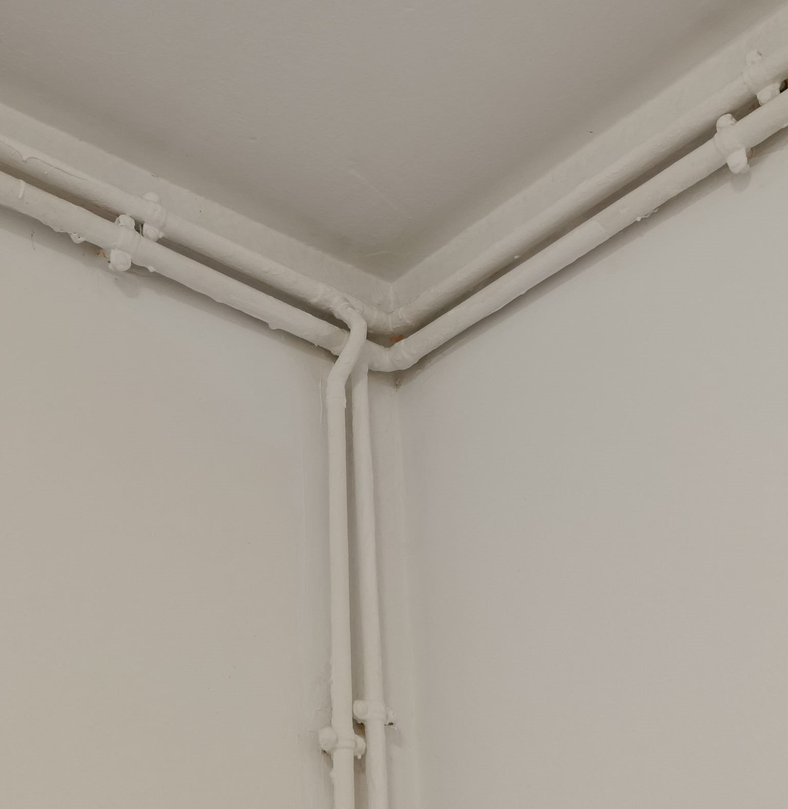
That said, ambient occlusion is not physically accurate, but rather an artistic approximation of a real-world phenomenon. It’s designed to enhance depth perception and spatial relationships in rendered images without simulating full global illumination 16.
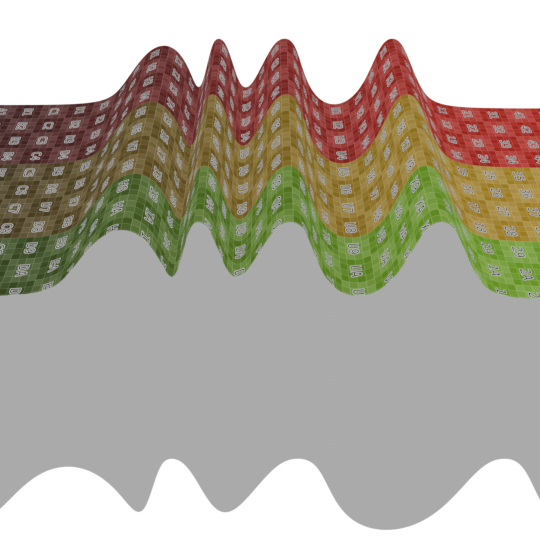
AO(p) is a scalar field with values usually between 0 and 1 over a surface. It encodes how much light is reaching at any point in the field. This technique is agnostic to the scene lights, therefore to calculate it we only need the geometry. As long as geometry doesn’t change, it can be baked.
In the world of games and other real time applications, it is common to only bake local ambient occlusion, meaning that only the self geometry of the object is used to calculate AO. If the object moves around the scene, the AO map does not need to change but there will not be any darkening on near by surfaces.
Ambient occlusion will take care of the contact shadows. It will not account for directional shadows cast by distant light sources like a window — it only simulates shadowing caused by nearby geometry.
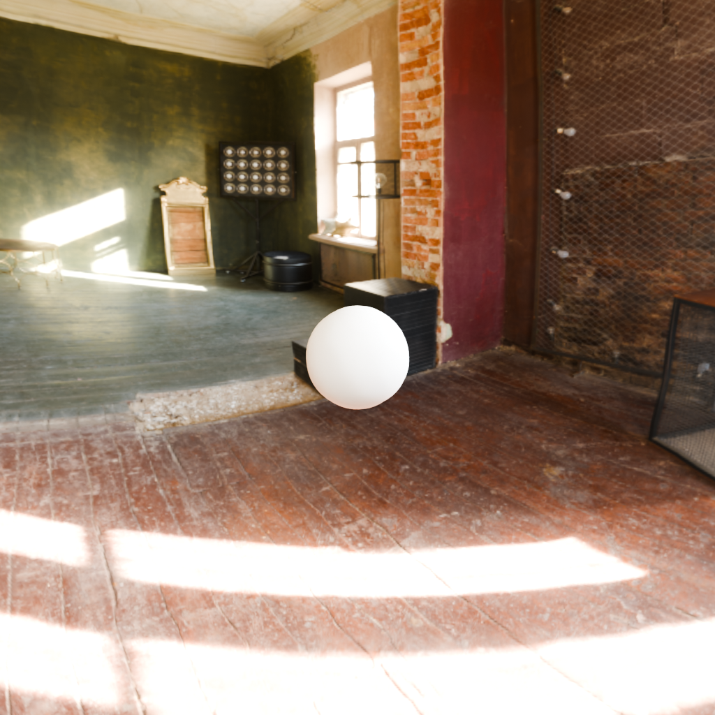
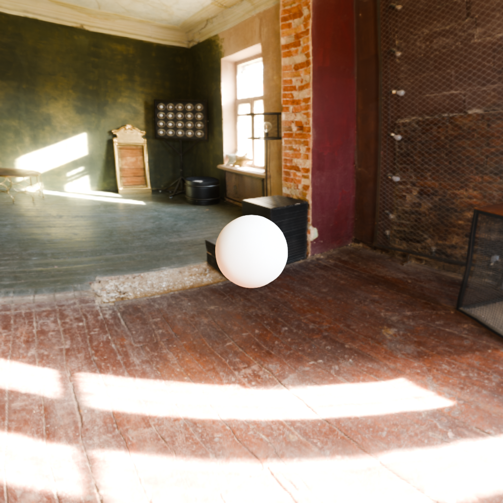
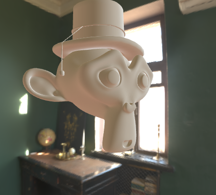
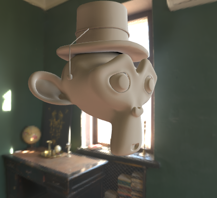
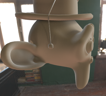
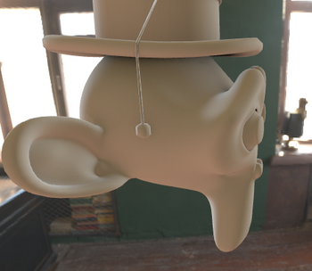
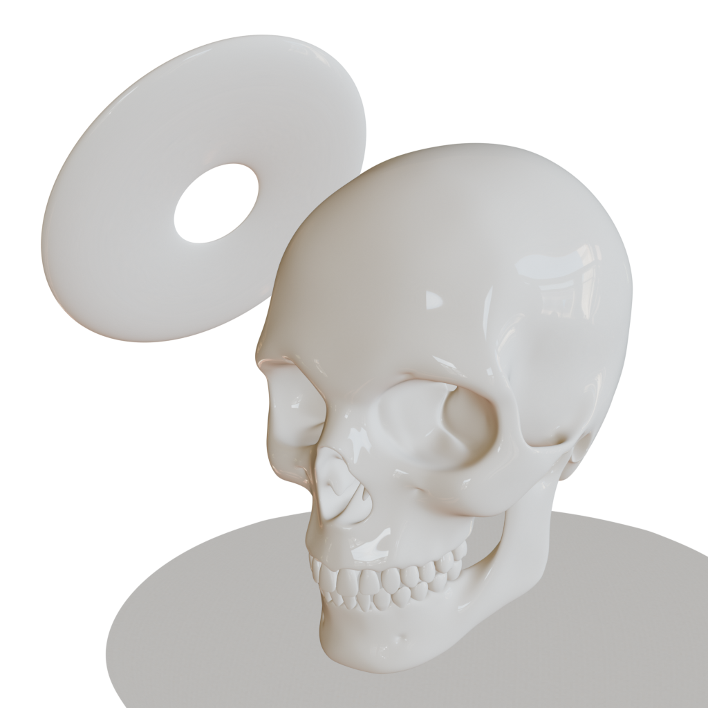
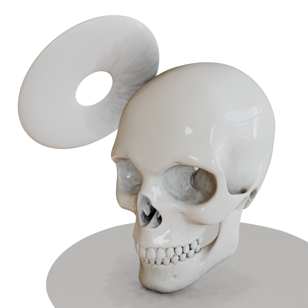
Let’s now compare the result with path tracing and Image Based Lightning+AO. The model Suzanne should have a shadow under the hat and also occlude light to his right ear.
We will use an Image Based Lighting Global Illumination technique where we project an image into the geometry based on its normal direction (diffuse lightning). All darkened and lighted areas will be provided from an irradiance texture of the environment.
For the path tracing, we assume the enviorment image are just millions of points irradiating light towards the object.
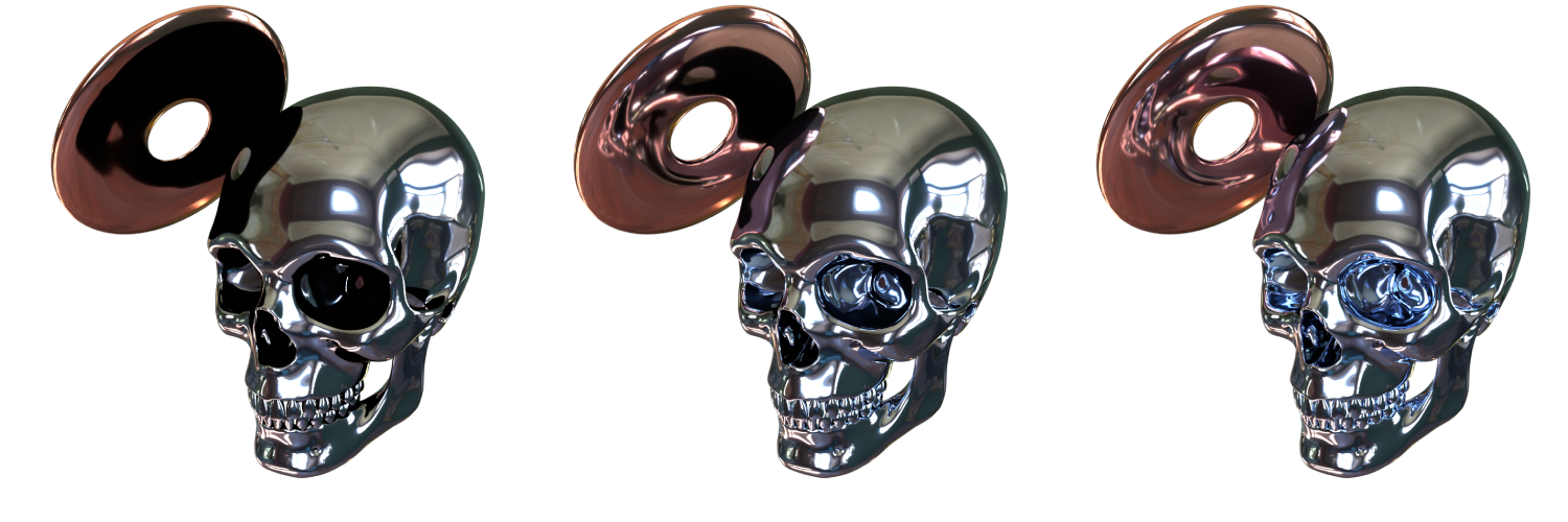
The following interactive example offers three slides:
- global_illumination: Image Based Lighting approach where we project an irradiance texture on the geometry based on surface normal direction.
- AO: Blocked light factor.
- shadow: Physically based rendered shadow.
We need all this three components to recreate what we would obtain with path or ray tracing. We are just simplifying the computation at the cost of visual quality.
Computation
You may have noticed that if Reflection Occlusion was already expensive on computation terms, calculating all rays in a hemisphere for each surface point would be prohibitive in real world applications. We will use a monte carlo simplification to only calculate a few rays for each point 9.
For more context we can look at the lambertian formula. You can also look at [2: Diffuse Irradiance; ; n.d.]:
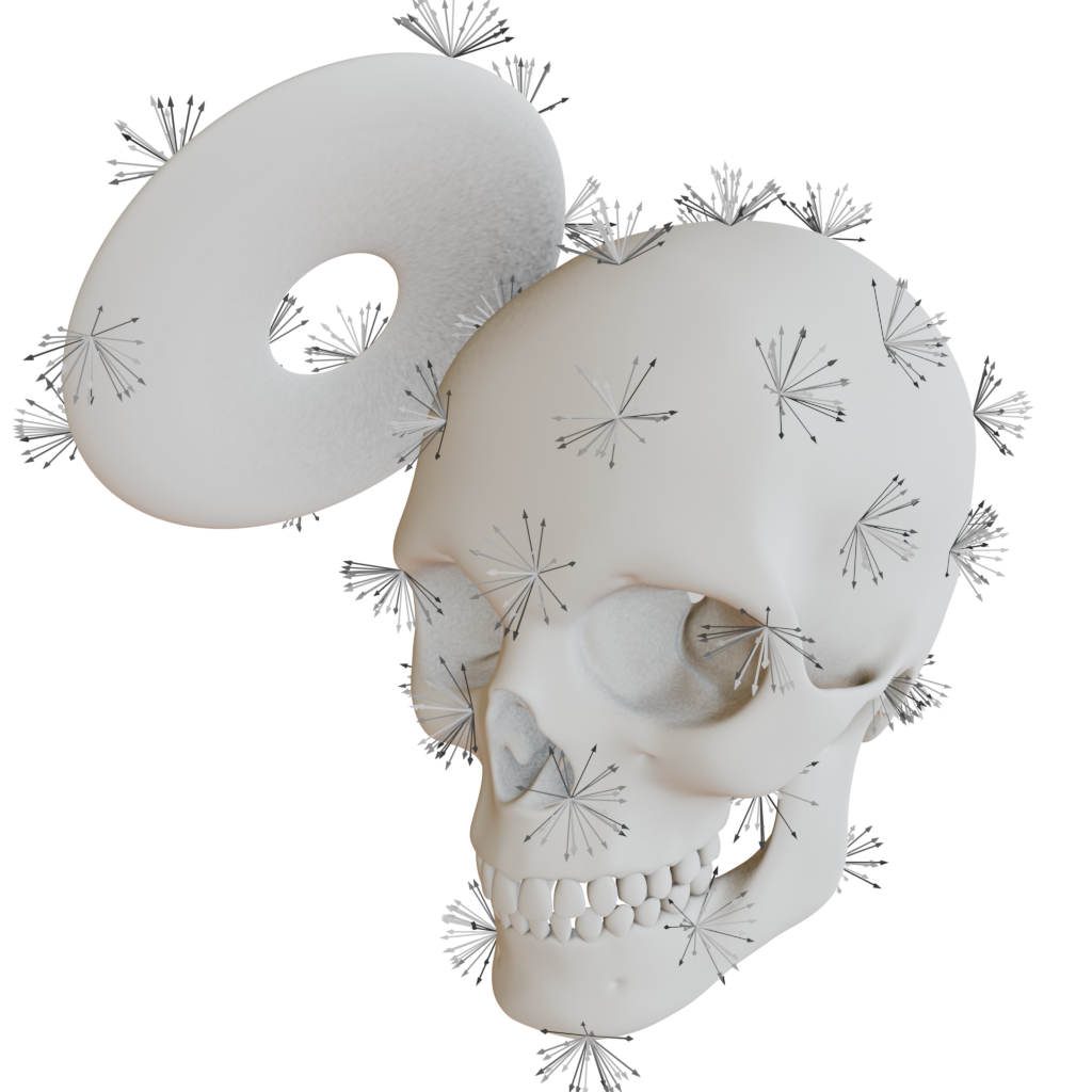
In Global Illumination, light hits a point from all directions 19, we must check occlusion on all directions too!!.
A basic algorithm to calculate Ambient Occlusion is to generate random vectors inside a hemisphere aligned with the fragment normal. We ray cast in those directions and store how many rays have been occluded. We average the result and store it in a texture.
An additional layer of realism would be to integrate lambert’s rule that states: the more aligned incident rays are with the fragment’s normal, the more they contribute to the final result.
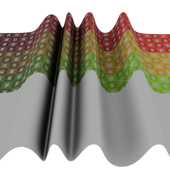
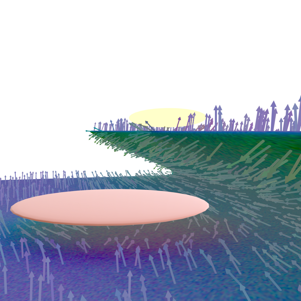
This technique is view independent therefore we can bake it and use it in any context as long as geometry does not change. In case the floating disk moved dynamically over time, we would have to recompute ambient occlusion for all geometry. This makes the technique invalid for real time applications with dinamic geometry.
Optional enhancements
We can go even further and register the mean direction of no-occlusion to later on color that fragment based on the bended normal direction of not occluded vectors. We can also detect the distance of the occluding object to weight length collision.
Where:
- $\mathbf{b}(p)$: Bent normal (mean not-occluded direction) at point $p$.
- $w_i$: Sampled direction in the hemisphere.
- $V(p, w_i)$: Visibility function (1 if not occluded, 0 if occluded).
- $M = \sum_{i=1}^{N} V(p, w_i)$: Number of not-occluded samples.
This formula averages all incident directions that are not occluded, resulting in the mean direction of unblocked ambient light.
Lets review what we got until this point and put names to this techineques:
- Ray traced AO: Realistic but requires Ray tracing only avalible on some GPU’s and of limited capacity (maybe a 100 rays for a hole sceene), too little resolution unless multiple passes. This technique can be used to bake textures but not for dynamic and real time applications.
- Hemispherical sampling: with some path traycing or ray tracing technique we check the occlusion on each surface point taking into account all directions on a hemisphere oriented in the normal direction.
- Bent normals/irradiance volume: we store the less occluded direction and use it to calculate the surface color.
- Baked AO maps in textures: once the above calculations are done, we proceed to store the result.
Conclusion

This is the basic idea behind Ambient occlusion. The combination of AO and RO on the different sides of PBR rendering provides a good starting point that can be improved further artistically.
As mentioned, there is a big computation requirement for this technique that prevents it’s use in real time. To solve this problem, a new set of techniques called Real Time Ambient Occlusion emerged. In exchange for accuracy, they archieve real time rendering on dynamic scenes that can not be backed. Usually they do not implement the reflection occlusion component since it requires too much computations that can not be avoided if we want a good result on the RO map.
Real Time Ambient Occlusion
When games entered in a graphics war they looked for applying AO in the gamplay. At first the only method known was to bake it for static elements of the scene.
For dynamic elements, the solution was to take into account only objects self geometry to calculate AO. The contact shadows of dynamic elements on the static ones was still an unsolved problem
SSAO
Screen space ambient occlusion techniques as the name suggest, will provide AO by using the screen space coordinates of the render. This provides a real time ambient occlusion calculation even though that it requires a few triks to perform fast that lead to less accuracy.
- basic SSAO
- HBAO/HBAO+
- GTAO
- SSDO
- VXAO
- SAO